The Pico Macro Keypad Walkthrough

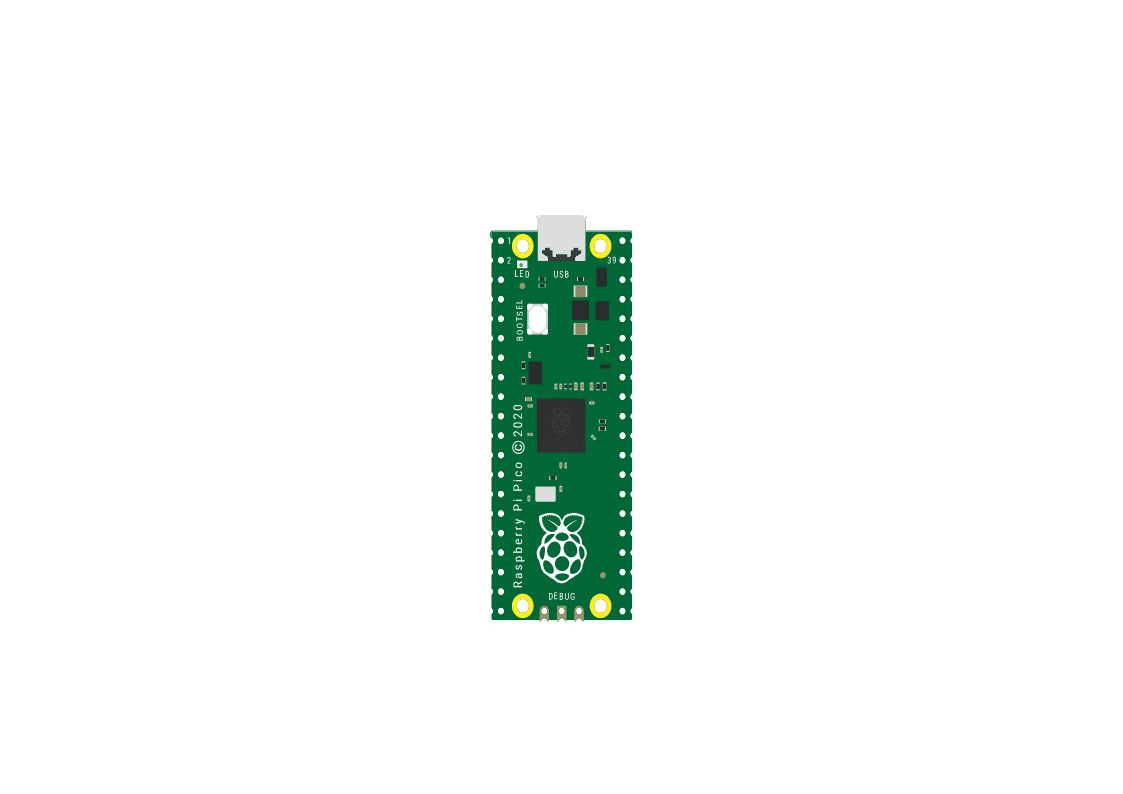
The Raspberry Pi Pico series is a range of tiny, fast, and versatile boards built using RP2040, the flagship microcontroller chip designed by Raspberry Pi. I used the rpi pico 1 but tested it on the pico w and it worked with no changes to the files or wiring.
What You Need To Print
------------------------
------------------------
What You Need To Have
------------------------
1 x Soldering Iron
1 x Wire Cutters
0.5 x Meter Solder
0.5 x Meter solid 22AWG wire
4 x M2x6 flat head self-tapping screws
4 x 6mm tactile buttons
1 x Micro Usb Cable
------------------------
1 x Soldering Iron
1 x Wire Cutters
0.5 x Meter Solder
0.5 x Meter solid 22AWG wire
4 x M2x6 flat head self-tapping screws
4 x 6mm tactile buttons
1 x Micro Usb Cable
Step 1
--------
3D print the necessary keyboard (1), keycap switches(4) and the tactile switch adapters(4).
Step 2
--------
Assemble the keyboard, placing the tactile switches inside of the adapters and then in the keyboard.
Step 3
--------
Cut a 10cm length of 22AWG wire and remove 1cm of the casing every 2cm. Solder the wire to the same posts on each of the switches and then to the ground.
Step 4
--------
Cut 4 5cm lengths of 22AWG wire and remove the wire from the ends. Solder the wires to the same posts on each of the switches and then to GP1, GP2, GP3 and GP4 respectively.
Step 5
--------
Assemble the tactile switches by placing the caps on the buttons. Plug in the micro usb cable and then use the self tapping screws to close up the keyboard. Push and hold the BOOTSEL button as you plug it into your computer.
Step 6
--------
Step 7
--------
Step 8
--------
Set the buttons to shortcuts and have fun! (works on both Windows and Linux[Ubuntu])
--------
3D print the necessary keyboard (1), keycap switches(4) and the tactile switch adapters(4).
Step 2
--------
Assemble the keyboard, placing the tactile switches inside of the adapters and then in the keyboard.
Step 3
--------
Cut a 10cm length of 22AWG wire and remove 1cm of the casing every 2cm. Solder the wire to the same posts on each of the switches and then to the ground.
Step 4
--------
Cut 4 5cm lengths of 22AWG wire and remove the wire from the ends. Solder the wires to the same posts on each of the switches and then to GP1, GP2, GP3 and GP4 respectively.
Step 5
--------
Assemble the tactile switches by placing the caps on the buttons. Plug in the micro usb cable and then use the self tapping screws to close up the keyboard. Push and hold the BOOTSEL button as you plug it into your computer.
Step 6
--------
Download the Circuit Python UF2 file fromhereand copy it to pico.
Step 7
--------
Download the pico macro keyboard file fromhereand then copy both the file (code.py) and the folder (lib) to the pico.
Step 8
--------
Set the buttons to shortcuts and have fun! (works on both Windows and Linux[Ubuntu])